| Save Preset File
|
Save settings from the "Merge Options" dialog in a file.
|
| Load Preset File
|
Load settings to the "Merge Options" dialog from a file.
|
| Elements to Process
|
Use to select the elements to process. Choose
between:
-
Vectors Only
-
Rasters Only
-
Reality Meshes Only
-
Point Clouds Only
-
All Elements
|
| Use Line Mapping
|
If processing the vector elements, a toggle is
available to use the current line mapping attributes.
If the Use Line Mapping toggle is turned ON the
line will be rasterized as defined in the current line mapping attributes.
If the Use Line Mapping toggle is turned OFF the
line will be rasterized as follows:
-
Line width of 0 ⇒ 1 pixel
-
Line width of 1 ⇒ 2 pixels
-
Line width of 2 ⇒ 3 pixels
-
...
-
Line width of 31 ⇒ 32 pixels
-
Line style of 0 ⇒ continue
-
Line style of 1 ⇒ 2; 6
-
Line style of 2 ⇒ 6; 2
-
Line style of 3 ⇒ 12; 4
-
Line style of 4 ⇒ 8; 3; 2; 3
-
Line style of 5 ⇒ 4; 4
-
Line style of 6 ⇒ 6; 2; 2; 2; 2; 2
-
Line style of 7 ⇒ 9; 2; 3; 2
Note that the numbers for line styles represent the
number of pixels for Dash; Gap; Dash; Gap…
|
| Create New Attachment(s)
|
Determine whether the new raster(s) will be
attached to the current model. The newly attached rasters will always have
their transparency and clipping toggles turned on.
|
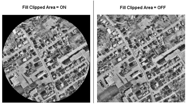
| Fill Clipped Area
|
The Fill Clipped Area option refers to howBentley Descartes handles
non-rectangular merge boundaries.
If selected, the clipped area will be filled with
the MicroStation
background color.
If off, the clipped area will be ignored and the
source rasters will be used to the extent of the clipping boundary.
|
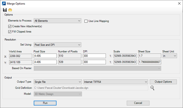
| Set Using
|
Select how to define the raster size and resolution.
The possible values are:
-
Pixel Size and DPI
-
Pixel Size and Scale
-
Pixel Size and Sheet Size
-
Number of pixels and DPI
-
Number of pixels and Scale
-
Number of pixels and Sheet Size
-
DPI and Scale
-
DPI and Sheet Size
-
Existing Raster
|
| Definition Fields
|
Text fields to display or edit the X and Y
resolution values.
The current Method selection determines which text
fields are editable and which are grayed out.
Each time a field is edited; all the other fields
are updated according to this new value.
By default:
-
World Area is calculated with the bounding box
around the selected area. The units of the world area values are the Model’s
working units.
-
Pixel Size is calculated by dividing the World
Area by the Number of Pixels. Also, the units of the pixel size values are
the Model’s working units.
-
Number of Pixels is set to the number of screen
pixels in the input area.
-
DPI is set to 300.
-
Scale is calculated by multiplying the Pixel
Size by the DPI.
-
Sheet Size is calculated by dividing the World
Area by the Scale. The World Area values must be converted to the same
units as Sheet Size multiplied by the DPI.
-
Sheet Unit is used to specify the units of the
Sheet Size fields only. (in, mm, or cm).
|
| Based On Raster
|
If the current Method selection is Existing
Raster, this field lists all the rasters that are included in the merge. It
also includes the option average. When a selection is done in this field, the
Definition Fields are updated using the geo-reference information of the
selected raster. The World Area and Pixel Size are always available in the
attachment. If the DPI is not available, 300 will be used by default.
|
| Output Type
|
Use to determine if the merge result is stored in a
single file or in multiple files.
When multiple files is selected, the user must
select a DGN and a model to define the shape of each output rasters to produce
and their file names. This DGN may not be in the same GeoCS than the master
DGN. In this case, the model will have to be re-projected before to define the
output raster areas.
|
| Output Options
|
Opens the Raster Save As Settings dialog allowing to
edit the Format, Options and Geographic Information for the output file(s).
|
| Grid Definition in
|
If multiple files is selected in the Output Type,
this field is enabled to allow setting the file used for the grid definition.
The magnifying glass displays the Open dialog to allow selecting a design file.
|
| Model
|
Lists the available models in the selected design
file.
|
| Run
|
Runs the merge operation.
|
| Cancel
|
Closes the dialog without making any changes.
|